In this article, we will dive into a brand-new Nokia network operating system – SR-Linux, which is available on a Nokia 7220 series. We will focus mainly on the basic L2 operations on this platform.
Topology
The topology for this article will consist of 4 devices:
- 2x Nokia SR-Linux nodes
- 2x Linux hosts
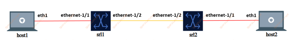
Each Linux host is connected to one SR-Linux node, and nodes are interconnected with each other. This way we can test the configuration for untagged and tagged traffic. The L2 link configuration is presented on the diagram, red connection stands for untagged traffic and orange for tagged.
Environment
To perform this lab, we’ll use Containerlab software. It’s based on Docker, and it can build a whole lab topology from the scratch based on a topology file. You can find more details on the project page.
And here’s our topology file.
name: srl-all

topology:
  kinds:
    srl:
      type: ixrd2
      image: srlinux:20.6.4-75
      license: license.key
    linux:
      image: ghcr.io/hellt/network-multitool
  nodes:
    srl1:
      kind: srl
    srl2:
      kind: srl
    host1:
      kind: linux
    host2:
      kind: linux
  links:
    - endpoints: ["srl1:e1-2", "srl2:e1-2"]
    - endpoints: ["srl1:e1-1", "host1:eth1"]
    - endpoints: ["srl2:e1-1", "host2:eth1"]
The topology file is available in the Gitlab repository.
It defines 2 Nokia SRLinux nodes and 2 Linux hosts.
In this scenario, we will use the ixrd2 chassis type for SR-Linux nodes, but there are several other types available for the L2 functionalities:
- ixrd1
- ixrd2
- ixrd3
The last section links defines wiring between hosts.
Configuration
The CLI of SR-Linux nodes is significantly different compared to the classic Nokia SR-OS.
First of all, after we login to the SR-Linux node, we’re placed in a running mode.

In this state, we can issue show commands, but we can’t perform any configuration changes.
To start our configuration journey, we need to switch to the candidate mode. We can do it by executing enter candidate command. After that, our prompt will inform us, that we’re now in candidate mode.

Now we’re ready to configure the interfaces!
Interfaces
Let’s list the desired configuration for our interfaces first:
- Ethernet-1/1: Interface facing Linux host, untagged packets in vlan 50
- Ethernet-1/2: Interface facing SR-Linux node, tagged packets in vlan 50
In the SR-Linux there is a concept of subinterfaces. To configure any vlan operations, we have to configure subinterfaces first. Let’s take a look at the ethernet-1/1.
  interface ethernet-1/1 {
        admin-state enable
        vlan-tagging false
        subinterface 50 {
            type bridged
        }
    }
In this configuration, after entering the interface configuration subtree, first of all, we’re administratively enabling this interface. Then we’re specifying that this interface is configured for untagged traffic.
In the SR-Linux, the L2 configuration is done directly on the subinterfaces, so we have to create one. In this case, we’re creating a subinterface with an ID of 50. The ID can be different, but I’ve chosen it for consistency’s sake. The last configuration step is to change the type of subinterface to bridged.
Let’s now take a look at the configuration of ethernet-1/2.
    interface ethernet-1/2 {
        admin-state enable
        vlan-tagging true
        subinterface 50 {
            type bridged
            vlan {
                encap {
                    single-tagged {
                        vlan-id 50
                    }
                }
            }
        }
    }
The first difference comparing to the ethernet-1/1 is a vlan-tagging parameter. Ethernet-1/2 will be configured to carry tagged traffic, so we have to specify it explicitly.
The subinterface structure is a bit more complex in this case. To force the interface to accept the tagged frames, we have to specify it. In this case, we’re accepting frames with vlan ID 50.
There are several limitations to the subinterfaces.
Each network interface (ethernet-slot/port) where the vlan-tagging parameter is set to false can have one subinterface, and the index number can be in the range 0 to 9999.
Each network interface where the vlan-tagging parameter is set to true can have up to 4096 subinterfaces (up ro 1024 of type routed and 3072 of type bridged) with each subinterface assigned a unique index number in the range 0 to 9999.
Official documentation
After entering the configuration, we can check the interface status with show interface brief command. Here’s the output.

As we can see, both ethernet-1/1 and ethernet-1/2 are in the down/down state, but we’ve enabled administratively those interfaces in the previous steps. It’s because our configuration changes are not committed yet. We have to execute the commit now command first. After the changes are committed, we can refresh the interface command.

Now we can see that both interfaces are operational.
LLDP
Since we have now working network interfaces between switches, let’s enable the LLDP protocol.
    system {
        lldp {
            admin-state enable
            interface ethernet-1/2 {
                admin-state enable
            }
        }
    }
After committing the changes we can get the LLDP neighbor’s information with show system lldp neighbor command.

Network-instance
Now let’s take a look at the network-instance configuration. Network-instances are named, in this case, I’ve used the vlan50 name for simplicity’s sake, but you can choose one that fits you best.
    network-instance vlan50 {
        type mac-vrf
        admin-state enable
        interface ethernet-1/1.50 {
        }
        interface ethernet-1/2.50 {
        }
    }
There are several types of network-instances, in this case, we just want simple L2 connectivity between devices, so we will use the mac-vrf. To provide connectivity between subinterfaces of ethernet-1/1 and ethernet-1/2, we have to add them to the network-instace with the interface command.
After committing the changes, we can display information about network-instance with show network-instance vlan50 summary
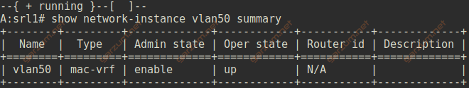
As we can see, the network instance is enabled and operational.
Troubleshooting
First of all, let’s jump to our two Linux hosts. For troubleshooting purposes, we will need an ip and mac address of each machine. We can grab that information with ifconfig command. Each Linux host has 2 network interfaces, we will focus on eth1.
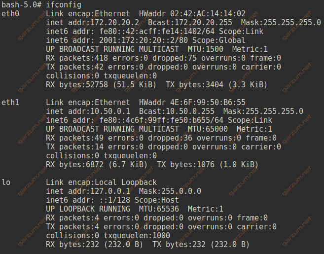
Host 1 details:
- ip – 10.50.0.1
- mac – 4E:6F:99:50:B6:55
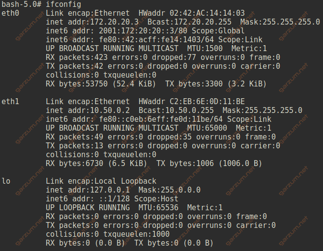
Host 2 details:
- ip – 10.50.0.2
- mac – C2:EB:6E:0D:11:BE
Mac-address table
Let’s now take a look at the mac-address tables of each SR-Linux machine.
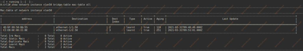
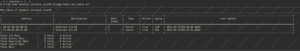
We do have the host mac address entries on the proper subinterfaces.
Let’s issue a ping command on host1 to test the end-to-end connectivity between two Linux machines.
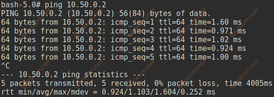
Everyting works as expected.
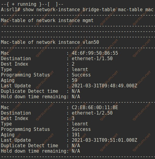
We can get more details about mac-address entries with show network-instance bridge-table mac-table mac command.
Interfaces
We can display a list of subinterfaces that are assigned to a particular network-instance with show network-instance vlan50 interfaces command.
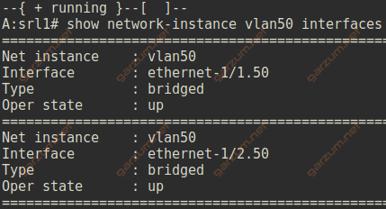
We’ve assigned two subinterfaces to the vlan50 network-instance, and they are visible in the output.
To grab more detailed information about the subinterface, we can use the show interface ethernet-1/1.50 detail command.
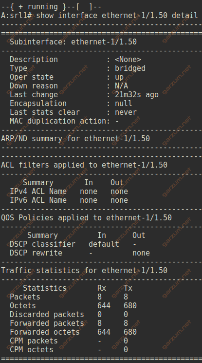
For the access subinterface ethernet-1/1.50 we can see, that the encapsulation is set to null. There are also sections with ACL, QOS, and statistics information.
Let’s now take a look at the ethernet-1/2.50 interface.
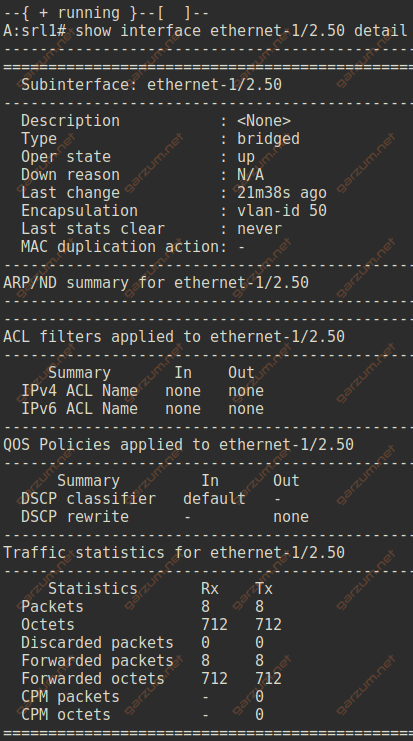
The output is similar, with one major difference. The encapsulation is set to vlan-id 50, which informs us, that this subinterface is operating on tagged frames with vlan-id 50.
We can also display information about physical interfaces with show interface ethernet-1/1 command.
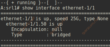
Besides the L1 information – speed and type, we have also L2 information – the encapsulation and type.
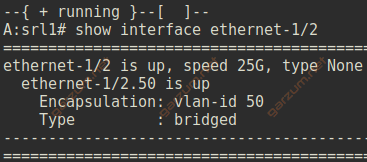
In case of trunk interfaces, we have a proper information about tagging.