In the previous article, I’ve shown how to configure layer 2 connectivity between the Cisco switch and Nokia router. There are however situations when you will be forced to find a non-standard solution due to the circumstances.
Imagine the following scenario:
You have to connect two new host devices to the existing network. Both devices have embedded IP and MAC addresses, so you cannot change them. Regardless of circumstances, you still want to manage those devices remotley.
Is this situation common? – Not really.
Is it bad? – Definitely, each MAC address should be unique.
But there is an easy solution to this problem. All you have to do is to place each device in the separate VLAN. From that point, if you have a virtual machine with matching VLAN, you can manage each host device.
But can this problem be more complicated? – Sure it can!
Now imagine that each device has embedded IP address, MAC address and is sending tagged packets on the same VLAN. You cannot change any of the above parameters, but you still want to manage those devices remotely.
What can you do in such a case? – If you have a normal layer 2 switch, after configuring a trunk on the interfaces to the hosts, there will be IP and MAC addresses conflict. Without any other action, communication won’t be possible.
A VPLS feature in the Nokia devices come in handy in such situations.
Configuration description
Basically, all we want to do is to bridge two different VLANs, to provide connectivity between the virtual machine and the end host. In the diagram below, you can see the logical connections that we want to configure.
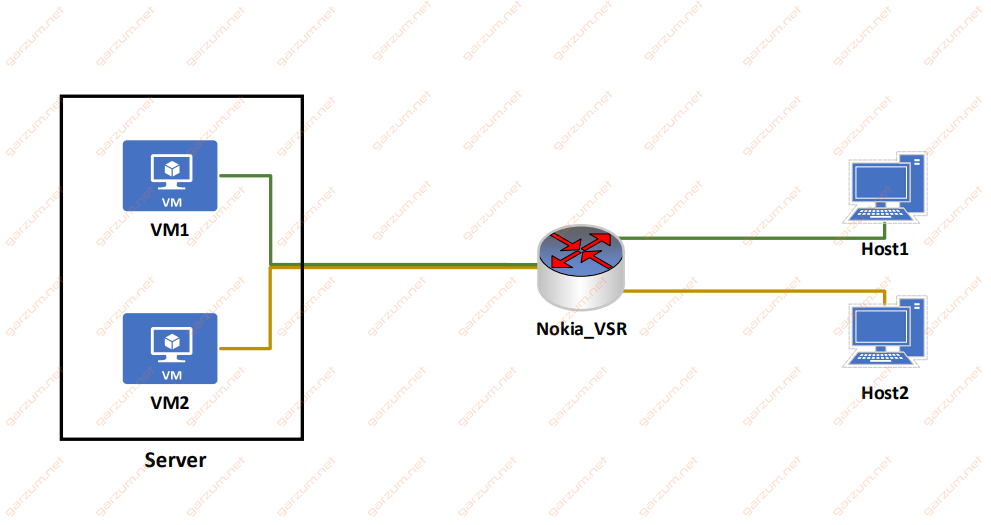
There are two virtual machines, that will be used to manage host devices:
VM1 – 192.168.0.2/24 – VLAN 100
VM2 – 192.168.0.2/24 – VLAN 200
Each host device has an IP address of 192.168.0.1/24 and is sending traffic with VLAN tag 2.
Keep in mind, that virtual machines can have same ip addresses, because they are separated with different VLANs, so there is no possibility for IP address duplication to occure.
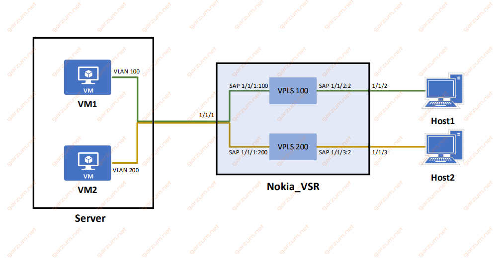
To establish a connection between host and virtual machine, we will create separate VPLS’es, one for each VM:
VPLS 100 – this VPLS will be responsible for the connection between the Host1 and VM1
VPLS 200 – similarly, this VPLS will be connecting VM2 with Host2
VPLS configuration
Configuration of both VPLS’es will be similar to one presented in this article. The main difference are SAPs.
In this case, we have to configure two SAPs per VPLS. Both of them will take tagged traffic from two different VLANs.
Before jumping to the VPLS section, remember to configure physical ports first.
The connection between VM1 and Host1
VM1 has assigned VLAN 100. This VLAN is unique in our small network, that’s why I’ll take it as a VPLS service id.
The virtual machine resides on the server, that is connected to the port 1/1/1. We only want traffic from the server, that is tagged with VLAN 100, so the first SAP will only receive frames on port 1/1/1 tagged with VLAN 100.
The end host is connected to the port 1/1/2. It’s also tagging packets, but in this case, with VLAN 2, so the second SAP will be receiving frames tagged with VLAN 2 on port 1/1/2.
Here’s the entire configuration of VPLS 100.
        vpls 100 customer 1 create
            description "VM1 <=> Host1"
            sap 1/1/1:100 create
            exit
            sap 1/1/2:2 create
            exit
            no shutdown
        exit
The connection between VM2 and Host2
VLAN 200 is also unique in the entire network, so the second VPLS will have an id of 200.
The first SAP will take traffic from VM1, so it will be configured on port 1/1/1, with tagged VLAN 200.
The Host2 machine is tagging traffic with VLAN 2, and it’s connected to the port 1/1/3, so the SAP will be configured for this particular traffic.
        vpls 200 customer 1 create
            description "VM2 <=> Host2"
            sap 1/1/1:200 create
            exit
            sap 1/1/3:2 create
            exit
            no shutdown
        exit
Down below you can find a graphical representation of our configuration.
Connectivity tests and troubleshooting
Let’s check first if both VPLSes are operational. To accomplish that, we will use the show service service-using command.
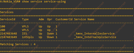
Both VPLSes are in the Up/Up state, which implies that they are fully operational.
Now we can move to the particular SAPs with the show service sap-using command.
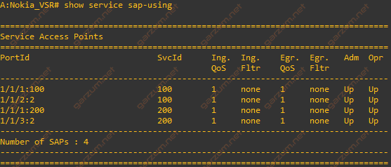
As with VPLSes, all SAPs are operational. On the screenshot, you can see which SAP is assigned to which VPLS(SvcId column). This information is very helpful during troubleshooting because you can clearly see, which SAPs can communicate with each other.
After checking VPLSes and SAPs, let’s check if connections actually working. First, let’s ping VM1 from the Host1.
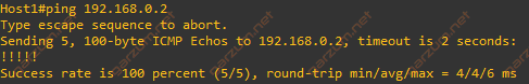
As you can see, ping is successful, so the connection is working as expected.
If you’re familiar with Cisco devices, you probably recognise the output from ping command issued on the Host1. It’s actually a Cisco switch. I’ve used it for this simulation due to the ease of configuration. Any host device sending described above traffic will behave same way.
Now, let’s check the second host.
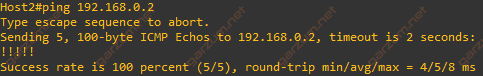
Ping is successful as well, so we can assume that configured connections are working.
Finally, let’s check the FDB MAC table with show service fdb-mac command.
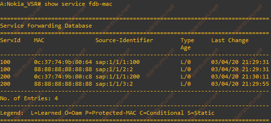
There are four MAC entries present. Two of them belong to the virtual machines (SAPs 1/1/1:100 and 1/1/1:200), and the remaining two represent the host devices.
As you can see, both host devices have the same MAC addresses and are sending traffic tagged with the same VLAN, but they are separated from each other and can communicate only with assigned virtual machines.