As network engineers, sometimes we have to deal with unusual problems. One of them is when we have two isolated IPv6 network parts, but we want them to be able to communicate with each other. In this article, we’re gonna address that.
Topology
In this scenario, we have 5 devices. Two Ubuntu PCs and three Cisco routers. The thing is, Ubuntu PCs are connected to the network only using IPv6, but the routers are interconnected with each other only with IPv4.
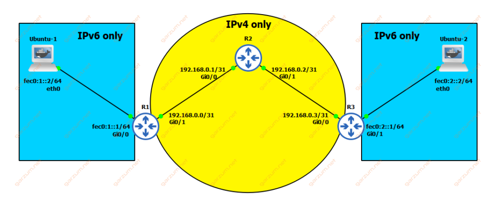
In such a scenario, there is no connectivity between Ubuntu-1 and Ubuntu-2. We have to find a solution to that problem. Let’s assume that we don’t have access to the R2, so we can’t implement a dual-stack on the whole network path.
Solution
As you’ve probably guessed from the article title, we will use the GRE tunnel based on IPv4, in which we will encapsulate IPv6 packets.
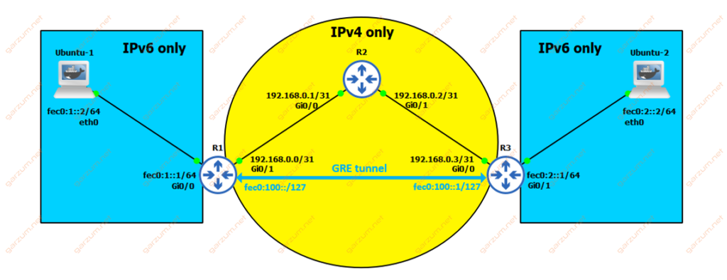
Tunnel endpoints will be terminated on R1 and R3. In this case, we will have IPv6 connectivity on the whole path between Ubuntu-1 and Ubuntu-2.
Connectivity check
Before diving straight to the configuration, it’s a good practice to check connectivity from one router, that will act as an endpoint, to the other. Let’s check if we have a route to the R3’s G0/0 interface subnet.
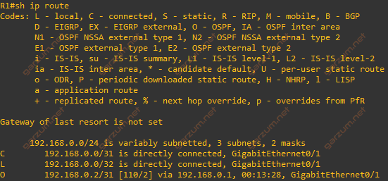
As we can see, the last entry stands for the 192.168.0.2/31 subnet, which is terminated on the link between R2 and R3.
Since we have the routing, let’s check connectivity by pinging R3.
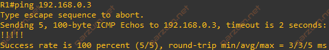
Connectivity is there, we can jump to the configuration of the GRE tunnel.
GRE tunnel configuration
Let’s start from R1. To make the GRE tunnel work, we need to configure three parameters:
- Addressation inside the tunnel
- Tunnel source
- Tunnel destination
interface Tunnel0
 description GRE_to_R3
 no ip address
 ipv6 address FEC0:100::/127
 tunnel source 192.168.0.0
 tunnel destination 192.168.0.3
Since we need the IPv6 connectivity inside the GRE tunnel, we’re configuring the point-to-point IPv6 network.
As a tunnel source, we’re specifying an ip address of the G0/1 interface, that’s facing R2.
For the tunnel destination, ip address of the G0/0 interface of R3 was chosen.
Now let’s move to the R3.
interface Tunnel0
 description GRE_to_R1
 no ip address
 ipv6 address FEC0:100::1/127
 tunnel source 192.168.0.3
 tunnel destination 192.168.0.0
Configuration is very similar. For the IPv6 address, we’re taking the second address of the point-to-point network.
Tunnel source/destination addresses are the same as on R1, but the configuration is mirrored. Source on R1 acts as a destination on R3 and so on.
Connectivity check
Since we’ve configured the GRE tunnel, we can check if it’s working as expected. Let’s ping R3 tunnel IPv6 address from R1.
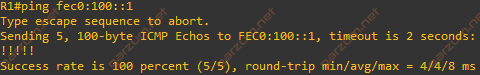
The ping is successful. Let’s check the information about the Tunnel0 interface.
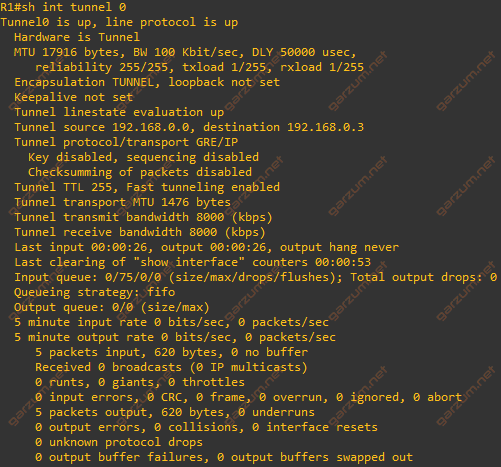
Besides the tunnel information, we can see in the statistics session, that there are 5 packets on the output, and 5 on input.
Routing over GRE tunnel
Now, as we have a working GRE tunnel with IPv6, we need to configure routing, so the R1 and R3 can forward traffic to PCs subnets properly. There are several ways to do it, the simplest is to use static routing, but we will configure the OSPFv3.
GRE tunnel supports multicast traffic, so dynamic routing protocols such as EIGRP or OSPF are working as normal, and there is no need for any special configuration. Let’s start with configuring OSPFv3 process on both routers.
router ospfv3 1
 exit
Now we can add proper interfaces to the OSPFv3. On R1 we need to add Tunnel0 and G0/0.
interface Tunnel0
 ipv6 ospf 1 area 0
 exit
!
interface GigabitEthernet0/0
 ipv6 ospf 1 area 0
 exit
!
On R3, the Tunnel0, and G0/1.
interface Tunnel0
 ipv6 ospf 1 area 0
 exit
!
interface GigabitEthernet0/1
 ipv6 ospf 1 area 0
 exit
!
Let’s check now the OSPF neighbors.
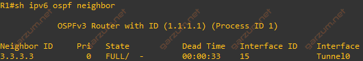
There is one neighbor with router-id of 3.3.3.3, as you can guess, it’s R3.
Now we can check the routing table if R1 received information about IPv6 subnet terminated on R3 – FEC0:1::/64.
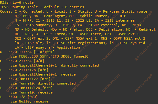
The first entry in the table informs us, that we’ve received a route from the OSPF protocol.
Let’s now check the end-to-end connectivity from Ubuntu-1 to Ubuntu-2.
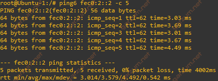
Ubuntu-2 is responding, the connectivity is there. Let’s also take a look at the traceroute from Ubuntu-1 to Ubuntu-2.
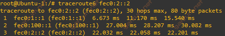
There are three hops. The first one is the default gateway, the second is the GRE tunnel interface of R3, and the third hop is Ubuntu-2 itself.
Packet analysis
The last thing in this article that I want to highlight is how the packets look like in the Wireshark. There are 10 packets captured during connectivity tests between Ubuntu-1 and Ubuntu-2. The packets were captured on the link between R1 and R2.
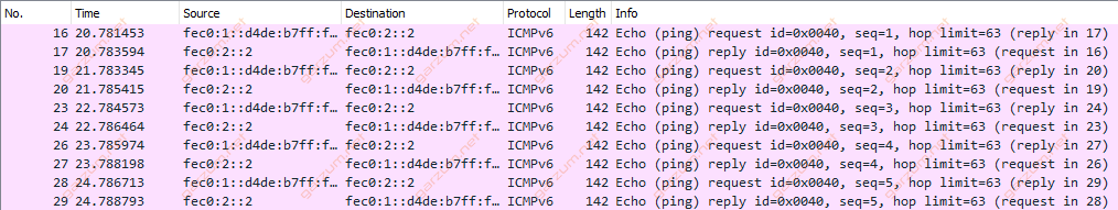
As we can see, there are IPv6 addresses visible at the first glance. Let’s take a look at the packet structure.
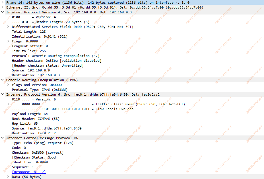
There are several headers, let’s examine that.
First, we have a layer 2 header with MAC information, nothing special. Then we have a layer 3 header, but if you take a closer look, it’s an IPv4 header. Then we have GRE information and the following header with IPv6 information. In the end, we have an ICMP.
This packet structure clearly shows how’s communication looks like. The IPv6 packets are traveling through the network on top of “classic” IPv4 packets.
You can clearly see, that whole packet is unencrypted. It means that the communication is visible to potential attacker.