In this article, I want to briefly touch on the Multiple Spanning Tree protocol configuration on Nokia 7750 and its compatibility with Cisco equipment. The spanning-tree configuration on SR-OS varies by type. The MST is slightly different because it uses User and Management VPLS’es. Let’s dive into that!
Topology
Today’s lab topology consists of 3 devices:
- Cisco-aggregation: standard Cisco L2 switch
- Nokia-aggregation: Nokia 7750
- Cisco-access: standard Cisco L2 switch
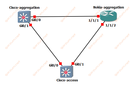
The Cisco-access switch is connected directly to the Cisco-aggregation and Nokia-aggregation. This topology gives us redundancy from the Cisco-access perspective, and of course a perfect L2 loop.
Scenario
Since we know how topology looks like, let’s look at the desired configuration.
Basically, we want to build a Multiple Spanning Tree protocol domain within our three devices. There will be 3 MST instances, Cisco-aggregation will be a root for MSTi 1, and Nokia-aggregation for MSTi 0 and 2.
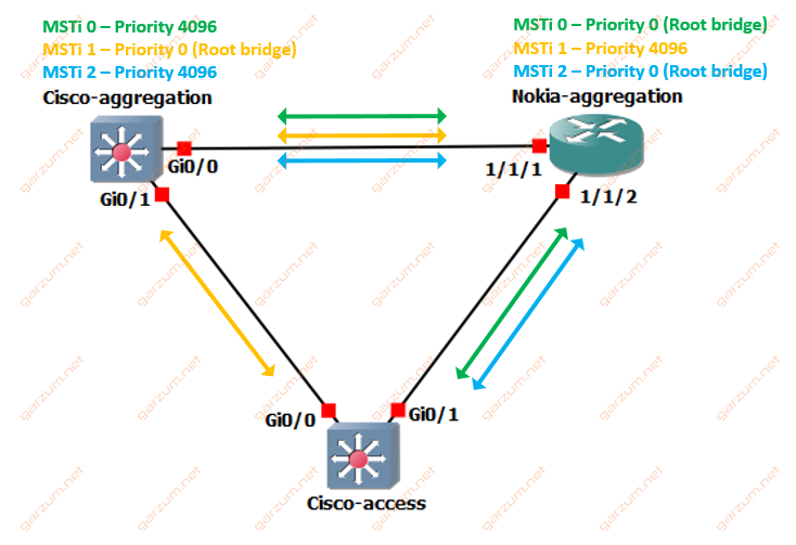
The presented configuration enables load balancing because the Cisco-access switch will forward frames directly to the root bridge of a particular MST instance. The traffic flow is presented in the diagram above.
Configuration
In this chapter, we will go through the configuration of each device, but first, let’s take a look at the Multiple Spanning Tree parameters.
Multiple Spanning Tree
The spanning-tree domain will be configured with following parameters:
- name: GarzumLab
- revision: 1
The MST instances are as follows:
- Instance 0: all vlans except 1-20
- Instance 1: vlans 1-10
- Instance 2: vlans 11-20
Be careful configuring Multiple Spanning Tree protocol parameters, they have to match on all devices within the domain.
Cisco-aggregation
First of all, let’s take a look at the configuration of Cisco-aggregation switch interfaces.
interface GigabitEthernet0/0
 description to_Nokia-aggregation
 switchport trunk allowed vlan 1-3,11-13
 switchport trunk encapsulation dot1q
 switchport mode trunk
!
interface GigabitEthernet0/1
 description to_Cisco-access
 switchport trunk allowed vlan 1-3,11-13
 switchport trunk encapsulation dot1q
 switchport mode trunk
!
They are configured as a standard trunk ports with allowed VLANs 1-3 and 11-13.
Let’s move to the MST configuration.
spanning-tree mode mst
spanning-tree extend system-id
!
spanning-tree mst configuration
 name GarzumLab
 revision 1
 instance 1 vlan 1-10
 instance 2 vlan 11-20
!
spanning-tree mst 0,2 priority 4096
spanning-tree mst 1 priority 0
It’s pretty straightforward. First, we have to define the name, revision, and next, we’re defining every MST instance. In the end, we’re setting proper priority for each instance according to the traffic flow diagram. Cisco-aggregation will be the root bridge for MSTi 1.
Nokia-aggregation
The configuration of the Nokia 7750 is a bit more complex compared to the Cisco equipment. First of all, we’re setting all ports to the access mode with encapsulation.
#--------------------------------------------------
echo "Port Configuration"
#--------------------------------------------------
    port 1/1/1
        ethernet
            mode access
            encap-type dot1q
        exit
        no shutdown
    exit
    port 1/1/2
        ethernet
            mode access
            encap-type dot1q
        exit
        no shutdown
    exit
After port configuration, we’re creating a VPLS’es. Each VPLS represents one VLAN. Since we’re using VLANs 1-3 and 11-13, we need to create 6 VPLS’es.
#--------------------------------------------------
echo "Service Configuration"
#--------------------------------------------------
    service
        customer 1 create
            description "Default customer"
        exit
        vpls 1 customer 1 create
            stp
                shutdown
            exit
            sap 1/1/1:1 create
            exit
            sap 1/1/2:1 create
            exit
            no shutdown
        exit
        vpls 2 customer 1 create
            stp
                shutdown
            exit
            sap 1/1/1:2 create
            exit
            sap 1/1/2:2 create
            exit
            no shutdown
        exit
        vpls 3 customer 1 create
            stp
                shutdown
            exit
            sap 1/1/1:3 create
            exit
            sap 1/1/2:3 create
            exit
            no shutdown
        exit
        vpls 11 customer 1 create
            stp
                shutdown
            exit
            sap 1/1/1:11 create
            exit
            sap 1/1/2:11 create
            exit
            no shutdown
        exit
        vpls 12 customer 1 create
            stp
                shutdown
            exit
            sap 1/1/1:12 create
            exit
            sap 1/1/2:12 create
            exit
            no shutdown
        exit
        vpls 13 customer 1 create
            stp
                shutdown
            exit
            sap 1/1/1:13 create
            exit
            sap 1/1/2:13 create
            exit
            no shutdown
        exit
    exit
Each VPLS has two SAPs, one represents a connection to the Cisco-aggregation and the second to the Cisco-access switch. Note that in each VPLS there is a spanning-tree protocol disabled. We will get back to it in a moment, but now, let’s verify if newly created VPLS’es are operational.
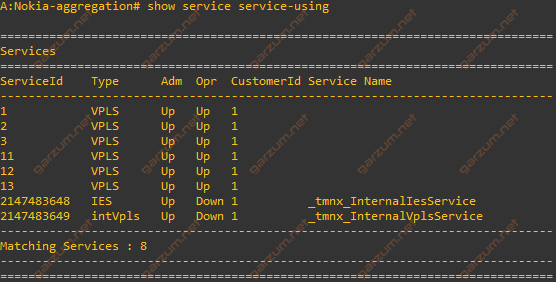
From the output of show service service-using we can assume, that everything is working as expected.
To configure Multiple Spanning Tree on Nokia 7750, we need to create a management VPLS. In the configuration of this service, we will be able to configure the MST properties.
        vpls 5000 customer 1 m-vpls create
            stp
                priority 0
                mode mstp
                mst-instance 1 create
                    mst-priority 4096
                    vlan-range 1-10
                exit
                mst-instance 2 create
                    mst-priority 0
                    vlan-range 11-20
                exit
                mst-name  "GarzumLab"
                mst-revision 1
                no shutdown
            exit
            sap 1/1/1:0 create
            exit
            sap 1/1/2:0 create
            exit
            no shutdown
        exit
In this case, we’ve created management VPLS with an ID of 5000. It has 2 SAPs assigned, one per each physical link. It’s worth to mention, that since we have access ports with encapsulation, we need specify encapsulation of :0 when defining an SAP. It will cause MST packets to be sent as untagged.
Now we’re ready to configure the STP tree. In the case of Nokia 7750, the configuration of MST instances is slightly different than Cisco. The priority command refers to the priority of MSTi 0. Next, the mode command defines a mode of spanning-tree protocol that is in use. Following that, we’re defining instances 1 and 2. In each subtree, we can define priority and the VLAN range. After that, we have to configure the remaining MST properties, the name, and revision.
Now we can check if the newly created VPLS is operational.
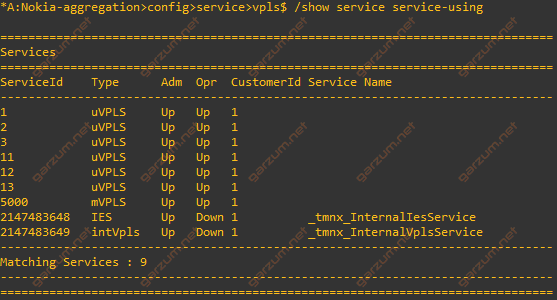
If we take a closer look at the output of show service service-using command, we can see, that type of our previously created VPLS’es has changed from the VPLS to the uVPLS, while the newly created VPLS is marked as mVPLS. The uVPLS stands for User Virtual Private Lan Service, and the mVPLS for Management Virtual Private Lan Service. As the name suggests the mVPLS’es are meant to manage the uVPLS’es.
Cisco-access
The configuration of the Cisco-access switch is very similar to the Cisco-aggregation. The interfaces are configured the same way.
 interface GigabitEthernet0/0
 description to_Cisco-aggregation
 switchport trunk allowed vlan 1-3,11-13
 switchport trunk encapsulation dot1q
 switchport mode trunk
!
interface GigabitEthernet0/1
 description to_Nokia-aggregation
 switchport trunk allowed vlan 1-3,11-13
 switchport trunk encapsulation dot1q
 switchport mode trunk
The MST is also configured the same way, besides the priority commands. We will leave the default priority of 32 768.
spanning-tree mode mst
spanning-tree extend system-id
!
spanning-tree mst configuration
 name GarzumLab
 revision 1
 instance 1 vlan 1-10
 instance 2 vlan 11-20
Verification
First of all, let’s check spanning-tree on the Cisco-aggregation switch.
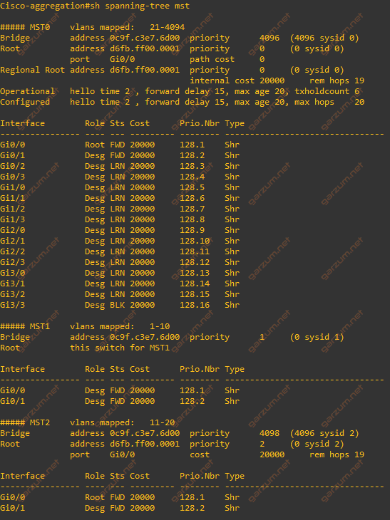
As we can see here, we’ve got information about all 3 MST instances. For instance 0, the mapped VLANs are 21-4094. The priority of Cisco-aggregation is 4096, but the root has priority 0, and the root port is G0/0, which is the interface, that Nokia-aggregation is connected to. The root of MSTi 1 is Cisco-aggregation, we can deduce it from the line Root: this switch for MST1. The two interfaces (Gi0/0 and Gi0/1) are designated ports, so everything is as expected. In the third instance, we can see that the root is again Nokia-aggregation with priority 0. The Cisco-aggregation has the priority of 4098 (4096 + MSTi number = 2).
Now let’s examine the Nokia-aggregation device. If we want to get the spanning-tree information for our VPLS’es, we have to refer to the mVPLS, in our case it’s a service 5000, so the verification command is show service id 5000 stp
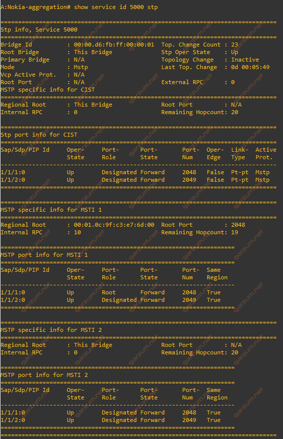
The output is divided into sections. In the first one, we’ve got information about CIST – Common Internal Spanning Tree. It’s a default spanning-tree instance of MST. It covers all VLANs, that are not assigned to the other instances. As we can see, we’re the root of CIST, first two SAPs have port-role of designated, which also informs us, that this device is a root.
The second section covers information for MSTi 1. In this case, the root bridge is Cisco-aggregation. From the output, we can get the root bridge ID, and also SAP facing the root bridge – 1/1/1:0.
The last section informs us about instance 2. Similar to the CIST, Nokia-aggregation is a root for this instance.
We now know how to interpret output directly from the mVPLS, but imagine now scenario if we have 2000 uVPLS’es configured on our device. How can we determine which uVPLS belongs to which mVPLS?
Let’s check that on the example of VPLS 2. In such a case, the show service id 2 stp detail command comes in handy.
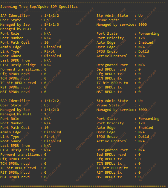
As we can see, in the block of each SAP, there is information about mVPLS, in this case – Managed by service: 5000. Having this information we can check all STP details directly on an mVPLS.
The last screenshot covers output from the Cisco-access switch.
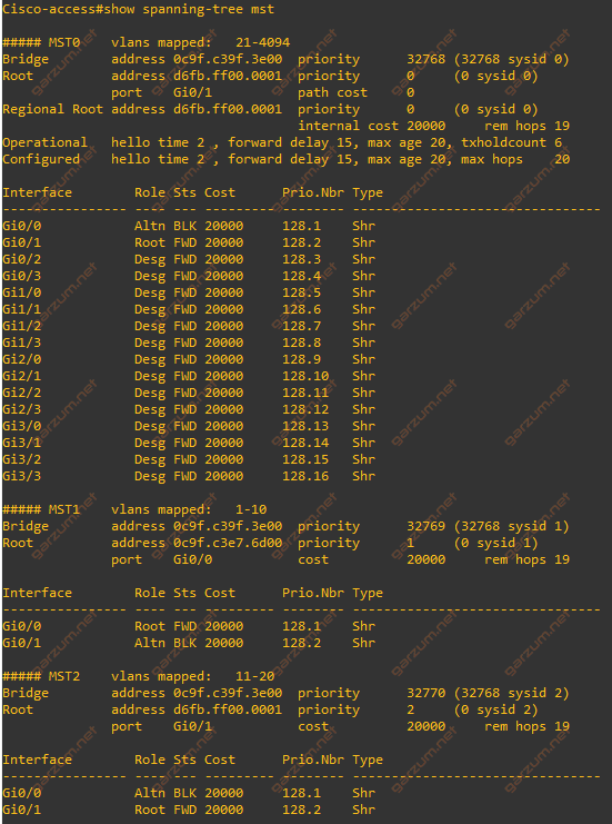
From the output, we can easily determine the traffic flow, which was presented on the diagram. For the MSTi 0 and 2 interface Gi0/0 is in a forwarding state, which means that traffic can flow through that interface. On the other hand, we have blocked interface Gi0/1, which is not forwarding any data traffic. In MSTi 1 the situation is similar, but the interfaces are the opposite – Gi0/1 is forwarding traffic, and Gi0/0 is in the blocking state.
Summary
I bet that the presented infrastructure – aggregation switch from Cisco and Nokia in one setup isn’t common, but I wanted to present the compatible MST configuration from the perspective of Cisco and Nokia OS.